Skills used
- Creo
- KiCad
- Vectors
- Arduino IDE
The Challenge
Design a robot using an arduino to complete a simple task
The Tech Stack
Microcontroller: Arduino Uno R3 Algorithm: PID Control Loop
Implementation
I wrote a C++ loop that reads the sensor values and calculates the error from the center line.
Hardware Design
Frame: Lasercut wood board Power 12 Volt battery
Video 1: Robot running in its earliest programming form
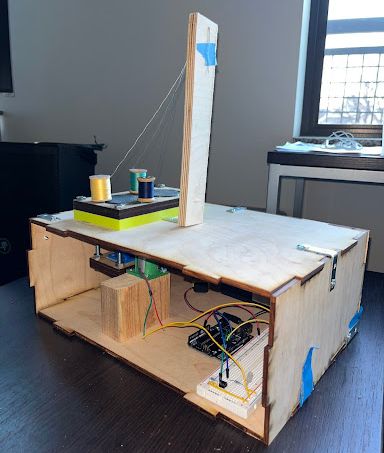
Figure 1: Side view of robot Figure 2: Model of internal mechanism of robot Figure 3: Early Sketch of how the spools of thread move in the robot Figure 4: Initial sketch of what the robot would look like when done Figure 5: Drawing of project wiring test, created using KiCAD


Arduino Motor Controller Code
// Pin Definitions
const int mainMotor = 3;    //Yellow wire
const int button = 4;       //Green wire
const int LED = 5;          //Blue wire


void setup() {
  // Set pin modes
  pinMode(mainMotor, OUTPUT);
  pinMode(button, INPUT);
  pinMode(LED, OUTPUT);

  digitalWrite(mainMotor,LOW);

}

void loop() {

  while (digitalRead(button) == HIGH){ //run until switch closes
    digitalWrite(LED,HIGH);
    delay(250);
    digitalWrite(LED,LOW);
    delay(750);
  }
  delay(2000);

  for (int i = 0; i < 4; i++) {
    digitalWrite(mainMotor,HIGH);
    digitalWrite(LED,HIGH);
    delay(5000);
    digitalWrite(mainMotor,LOW);
    digitalWrite(LED,LOW);
    delay(250);
  }

  delay(500);
}